apa yang sedang Anda cari?

Quick Answer: Exhaust sensor wiring should be protected by controlling routing, maintaining clearance from hot exhaust components, securing the cable against vibration and using an appropriate thermal sleeve or connector shield where radiant heat remains significant. Aluminized fiberglass sleeves are particularly useful where the dominant thermal load is radiation from an exhaust manifold, turbocharger, catalytic converter, DPF or SCR system. The sensor lead, connector and transition into the main harness should all be evaluated rather than protecting only a short section of cable.
Oxygen sensors, exhaust gas temperature sensors, NOx sensors, exhaust pressure sensors and other emissions-system sensors must operate close to some of the hottest parts of a vehicle.
The sensing element may be designed for the exhaust environment, but the attached electrical lead, connector, control module and main vehicle harness normally need a much lower thermal environment.
This creates a specific thermal-management problem: the sensor must remain close enough to the exhaust system to perform its function while the associated electrical components need protection from radiant heat, hot airflow, vibration, abrasion and contamination.
A correctly designed sensor wire heat shield therefore protects more than the cable jacket. It should be considered as part of the complete routing and retention system.
BSTFLEX manufactures aluminized heat protective sleeves for sensor leads, automotive wire harnesses, hoses, cables and fluid lines exposed to radiant heat.
A conventional engine-bay wire harness can often be routed away from the hottest exhaust components.
Exhaust sensors do not have that freedom.
The sensor itself may need to be installed directly in or immediately beside:
The electrical lead therefore begins inside a severe thermal zone and must transition toward a cooler connector and vehicle harness location.
That transition needs to be engineered deliberately.
The exact sensor arrangement depends on the engine and emissions system, but common thermally exposed electrical components include:
Each assembly can have different cable, connector and electronics requirements, so one generic sleeve specification should not automatically be applied to every sensor.
A useful engineering approach is to divide the electrical assembly into three thermal zones.
This is the section closest to the exhaust component.
It typically experiences the highest radiant heat and may also be exposed to vibration, hot airflow and road contamination.
The connector may be physically larger than the sensor cable and can contain seals, plastic housings and terminal-retention components with different temperature limitations.
This zone is frequently overlooked when only a narrow cable sleeve is specified.
After the sensor wiring reaches a cooler part of the vehicle, it normally joins or connects to a larger engine or chassis harness.
Protection requirements may reduce significantly at this point, but routing and retention are still important.
Engineering point: Protecting 100 mm of sensor cable does not solve the application if the connector immediately outside that sleeve remains exposed to the same radiant heat source.
Oxygen sensors are installed directly in exhaust manifolds, catalytic-converter assemblies or exhaust piping depending on the vehicle configuration.
The sensor lead therefore begins at a very hot component and must be routed toward the electrical connector without contacting the exhaust system.
An oxygen sensor wire heat shield may be required where routing alone cannot provide sufficient thermal separation.
Important design factors include:
The cable should not be allowed to sag toward the exhaust after installation.
Upstream and downstream oxygen sensors can experience different thermal environments.
An upstream sensor may be located close to the exhaust manifold or first catalyst where packaging is extremely tight.
A downstream sensor may be farther along the exhaust system but can still operate near a catalytic converter or hot pipe section.
Do not assume that the same protected length or sleeve configuration is suitable for both locations.
Measure each routing separately.
Exhaust gas temperature sensors are intentionally positioned in locations where exhaust temperature needs to be measured.
The probe can tolerate the intended exhaust environment, but the electrical lead must transition away from that high-temperature location.
An EGT sensor wire heat sleeve can be used where the cable remains exposed to radiant heat after leaving the sensor body.
Typical considerations include:
The sleeve should not interfere with sensor removal, installation or service access.
NOx sensors are commonly associated with exhaust aftertreatment systems and can be positioned before and after SCR-related components depending on the system architecture.
The wiring assembly may include a sensor cable, connector and electronics module.
Thermal protection therefore needs to account for the full component layout rather than shielding only the probe-side lead.
A NOx sensor cable heat protection system should consider:
Where the wiring is routed close to the aftertreatment assembly, a local reflective sleeve or shaped shield can reduce radiant exposure while the main cable is routed toward a cooler mounting area.
Exhaust and differential-pressure sensor systems can include small tubes, sensor bodies and electrical wiring located around exhaust-aftertreatment components.
The electrical connector may require localized shielding even where the sensor itself is mounted away from the exhaust pipe.
In these installations, review both:
A shaped connector shield may sometimes be more appropriate than a long tubular sleeve.
Exhaust systems produce strong radiant heat.
Radiant heat can raise the temperature of sensor wiring even when the cable never touches the exhaust surface.
This is the primary condition where an aluminized reflective sleeve can be useful.
The metallic outer surface reflects a portion of the radiant energy before it is absorbed by the underlying fiberglass structure and protected cable.
For more detail on this construction, see Aluminized Fiberglass Sleeve for Automotive Wire Harness Protection.
A reflective sleeve should not be selected solely because the exhaust component has a high temperature.
The heat-transfer mechanism matters.
| Thermal Condition | What Happens | Design Response |
|---|---|---|
| Radiant heat | Heat travels from the exhaust surface across a gap | Reflective aluminized protection can be effective |
| High ambient temperature | The surrounding engine or aftertreatment area remains hot | Consider complete sleeve insulation and exposure duration |
| Direct contact | The cable or sleeve touches the hot exhaust component | Correct routing first; conductive heat requires separate evaluation |
| Hot airflow | Heated air moves around the cable and connector | Protect the complete affected zone rather than one point |
The first protection method should normally be correct routing.
A heat sleeve should not be used as an excuse to route sensor wiring directly against a hot exhaust component when additional clearance is available.
Review minimum clearance to:
Clearance should be checked under operating conditions, not only when the engine and exhaust system are cold.
Exhaust components expand as they heat.
A cable that appears to have adequate clearance during assembly may experience reduced clearance during operation.
Engine and exhaust movement can also change the relationship between the cable and heat source.
Evaluate:
The minimum operating clearance is more important than the cold static clearance.
Thermal protection cannot compensate for mechanical damage.
A sensor cable routed through a high-temperature zone can also be exposed to:
Prevent rubbing before adding the thermal sleeve.
If both heat and abrasion are significant, the protective construction should address both risks.
The position of the sensor cable should remain controlled throughout vehicle operation.
Suitable retention can prevent the wiring from falling toward a hot exhaust component.
Depending on the vehicle design, retention may include:
The retention system should not create excessive bending or pressure on the sensor lead.
An aluminized sleeve is usually a logical starting point where:
Possible constructions include:
Sensor wiring can be considerably smaller than a main engine harness.
An oversized sleeve may:
Measure the actual finished sensor cable OD rather than selecting the sleeve from a generic wire size.
The sensor connector can be much larger than the cable.
This is especially important when considering a tubular slide-on sleeve.
Ask:
If the connector prevents tubular installation, an openable sleeve or custom-shaped shield may be more appropriate.
Vehicle wiring is frequently already terminated before thermal protection is installed.
In that situation, a wrap-around design can be installed without removing the connector.
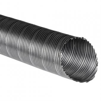
BSTFLEX Heat Shroud Aluminized Sleeving with Hook-and-Loop Closure can be wrapped around existing wires, cables and hoses without requiring the complete assembly to pass through a tube.
This construction can be useful for:
A self-closing sleeve provides another installation option for finished cable assemblies.
The sleeve opens to accept the cable and then closes through its overlapping structure.
BSTFLEX Self-Closing Aluminum Foil Fiberglass Sleeve can be considered where fast installation over a completed wire bundle is required.
The cable OD must remain within the usable closing range so that the reflective layer continues to provide complete coverage.
A conventional sleeve is not always the best solution for sensor connectors or electronic modules.
Irregular components may have:
In these cases, a shaped thermal cover can provide better coverage than simply using an oversized tube.
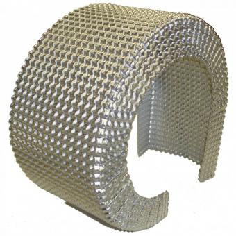
BSTFLEX Custom-Shaped Aluminized Fiberglass Automotive Heat Shield can be developed around sensors, connectors, valves, wire harnesses and other irregular automotive components.
Diesel aftertreatment systems combine multiple high-temperature components within a relatively small underbody or chassis area.
Depending on the system, sensor wiring may pass near:
The routing may therefore combine electrical wires, fluid lines and sensor tubes.
Thermal protection should be planned as a system rather than treating each cable in isolation.
BSTFLEX also covers this type of environment in DEF Injector Feed Line Heat Shield for Exhaust Thermal Protection.
Turbocharger installations can expose sensor leads to intense localized radiant heat.
Possible risks include:
A reflective sleeve may be suitable for the sensor cable, but the connector should also be positioned outside the highest thermal zone wherever possible.
If the sensor lead itself is designed for a relatively severe environment, the connector may become the limiting component.
Before extending the sleeve indefinitely, identify:
Moving the connector a short distance into a cooler area can sometimes be more effective than adding another layer around an incorrectly positioned connector.
Oxygen, EGT, NOx and other exhaust sensors may need to be removed during inspection or service.
The thermal protection system should not make normal sensor replacement unnecessarily difficult.
Consider:
Openable or removable thermal protection may be preferable where sensor replacement is expected during vehicle service life.
A sleeve should not add so much bulk that the cable is forced closer to the exhaust system.
This is especially important in tight spaces around:
Always check the final installed envelope after adding the sleeve.
The reflective aluminized surface should normally face the external radiant heat source.
Installation should avoid:
A reflective sleeve and an exhaust component form part of a thermal system.
When the sleeve faces the hot component across a gap, radiant heat is the primary concern.
If the sleeve touches the hot component, conduction becomes much more important.
For this reason, sleeve performance should not be discussed without considering:
Sensor wiring can experience more than heat.
Depending on its position, the sleeve may encounter:
Fluid and environmental resistance should be evaluated for the complete proposed sleeve construction, including the reflective layer, adhesive, sewing thread and closure.
Exhaust sensor wiring often experiences continuous vehicle vibration.
A sleeve that performs well thermally can still fail if it rubs against a metal edge.
Inspect:
If severe abrasion is expected, the design may require additional mechanical protection rather than relying only on a reflective layer.
| Application | Typical Thermal Concern | Recommended Starting Approach |
|---|---|---|
| Oxygen sensor near exhaust manifold | Strong radiant heat near sensor lead | Controlled routing plus aluminized reflective sleeve |
| Downstream oxygen sensor | Catalytic-converter and exhaust-pipe heat | Reflective cable protection with secure retention |
| EGT sensor near turbocharger | High local radiant heat and vibration | Reflective or multi-layer cable sleeve |
| NOx sensor near SCR system | Aftertreatment heat and underbody environment | Local reflective protection plus controlled connector placement |
| Exhaust pressure sensor connector | Localized radiant heat near connector | Connector shield or shaped thermal cover |
| Completed sensor harness with large connector | Cannot slide tubular sleeve over connector | Wrap-around or self-closing sleeve |
| Irregular sensor/control module assembly | Complex geometry | Custom-shaped heat shield |
For a tubular or wrap-around sensor sleeve, record:
For an irregular connector, provide photographs or a drawing rather than trying to describe the component with one diameter.
There is no universal protected length.
The sleeve should extend across the complete heat-affected portion of the cable.
Define the protected zone by reviewing:
Do not stop the sleeve simply because the cable turns away from the sensor if it remains inside the same high-temperature environment.
The sleeve ends immediately before a plastic connector positioned in the same radiant heat zone.
The cable has adequate clearance when installed but moves toward the exhaust after vibration or clip movement.
The sleeve rotates, moves or contacts nearby exhaust components.
A heat sleeve is added instead of relocating the cable away from a sharp bracket or hot surface.
The sleeve touches the exhaust component even though it was selected for radiant heat shielding.
The sensor cannot be removed without destroying the thermal protection assembly.
Upstream, downstream, engine-bay and underbody sensors can have substantially different thermal and mechanical conditions.
For OEM applications, the proposed sleeve should be evaluated in a representative installation.
Relevant test inputs can include:
The objective should be to verify the temperature of the protected electrical components, not simply demonstrate that the sleeve material survives the test.
| Item | Information Required |
|---|---|
| Sensor type | Oxygen, EGT, NOx, pressure or other exhaust sensor |
| Sensor location | Manifold, turbo, catalyst, DPF, SCR or pipe position |
| Cable OD | Normal and maximum finished dimensions |
| Connector dimensions | Width, height and cable exit position |
| Heat-source temperature | Normal and peak where available |
| Minimum clearance | Operating distance from exhaust component |
| Maximum cable temperature | Required protected-component limit |
| Maximum connector temperature | Connector-specific requirement |
| Protected length | Full thermally exposed routing section |
| Installation sequence | Before or after connector installation |
| Retention method | Clips, ties, brackets or integrated attachment |
| Environmental exposure | Oil, water, chemicals, road splash or abrasion |
| Service requirement | Permanent or removable protection |
| Annual quantity | Prototype and production volume |
| Validation requirement | OEM drawing, customer specification or applicable test method |
BSTFLEX manufactures flexible thermal protection components for automotive sensor wiring, wire harnesses, cables, hoses and fluid lines.
Available constructions include:
Custom manufacturing can include:
For general automotive harness protection, see Automotive Wire Harness Heat Protection Sleeves: Materials, Designs and Applications.
For aluminized sleeve materials and constructions, see the BSTFLEX Aluminized Heat Protective Sleeve category.
For an exhaust sensor wiring thermal-protection project, send:
Installation drawings and photographs are particularly useful because sensor wiring thermal problems are strongly influenced by routing and local geometry.
First maintain the greatest practical distance from the exhaust and secure the cable so it cannot sag toward the hot surface. Where radiant heat remains significant, an aluminized reflective sleeve can be installed over the thermally exposed cable section.
Yes, but connector geometry and service access need to be considered. A custom-shaped or wrap-around shield may fit a large connector better than an oversized tubular sleeve.
An aluminized fiberglass sleeve is a useful starting point where radiant exhaust heat is the dominant problem. Final selection depends on source temperature, clearance, cable temperature limit, vibration and environmental exposure.
NOx sensor assemblies can be located around exhaust-aftertreatment systems. Whether additional protection is required depends on routing, clearance, connector position and the thermal requirements of the specific sensor assembly.
A reflective aluminized sleeve is primarily intended for radiant heat protection. Continuous contact introduces conductive heat and should trigger a review of cable routing, clearance and insulation construction.
Yes. For an aluminized reflective construction, the metallic surface should normally face the external radiant heat source.
Yes. Wrap-around, hook-and-loop and self-closing constructions can protect many completed sensor cable assemblies without passing the connector through a tubular sleeve.
Measure the finished cable outside diameter, maximum local diameter, connector dimensions and protected length. For a tubular sleeve, also confirm whether the connector must pass through the sleeve during installation.
No. Cable temperature depends on heat-source temperature, distance, exposure time, airflow, shielding, sleeve construction and routing. The exhaust temperature alone does not define the sensor-wire temperature.
Yes. BSTFLEX can develop component-specific shields from drawings, photographs, dimensional data or physical samples, including custom shapes, closures, cutouts and insulation layers.
Sensor wiring near an exhaust system should be treated as a complete thermal-routing problem rather than simply a cable that needs a higher temperature sleeve.
The best design combines:
Where radiant heat from an exhaust manifold, turbocharger, catalytic converter, DPF or SCR assembly remains significant, an aluminized fiberglass sleeve or custom-shaped reflective shield can provide localized protection for the sensor lead and connector.
For OEM projects, send BSTFLEX the sensor assembly drawing, cable and connector dimensions, heat-source data, clearance, target component temperatures and annual quantity so the protection system can be developed around the actual installation.

No.10, Chuangxin North Road, Nanshan Park, Ningguo Economic and Technological Development Zone, Ningguo City, Anhui Province, China
telp/Whatsapp : 0086-15856303740
surel : sales@bstbraidedsleeve.com
Skype : vanesa-cheng